VLANS circa 1998 Link to heading
It’s amazing that a technology that is over 16 years old is still widely used today. Why? Because it works in most cases (small/medium datacenters, single/dual tenant design, etc). However, due to the growth of cloud computing, the need for secure, scalable virtual networks has changed. Although some solutions exist today to help facilitate some of the isolation concerns, such as QinQ, they fail to address the increasing issue with scale. Virtual Extensible Local Area Network (or VXLAN) extends the VLAN concept of a layer 2 (L2) domain but allows it to sit on top of (overlay) your existing network. It uses MAC-in-UDP encapsulation to create tunnels (VXLAN Tunnel Endpoints or VTEPS) across a layer 3 (L3) transport to extend your L2 domain with great flexibility. This would allow for hosts to live in two disparate networks yet still operate as if they were attached to the same L2 domain. This also solves the VLAN limitation of 4096 VLAN ID’s as VXLAN supports over 16 million VXLAN id’s. I’ll provide a quick overview on how this technology works, some of the misconceptions surrounding it, as well as current adaption methods.
The Basics Link to heading
VXLAN is an L2 overlay over an L3 network. Each overlay network is known as a VXLAN segment and identified by a unique 24-bit segment ID called a VXLAN Network Identifier (VNI). Only hosts on the same VNI are allowed communicate with each other. Hosts are identified uniquely by the combination of their MAC addresses and VNI. As such it is possible to have duplicate MAC addresses in different VXLAN Segments without issue, but not in the same VXLAN segments. Confused yet? :)
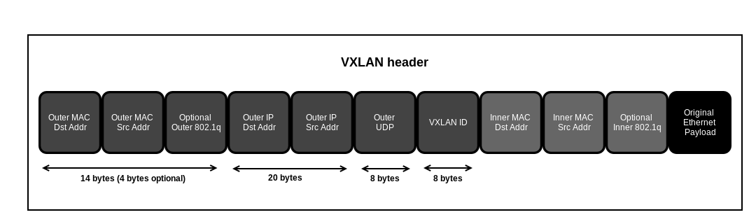
The Header Link to heading
The encapsulation consists of the following:
- Ethernet Header
- IP Header
- UDP Header
- VXLAN Header
Ethernet Header Link to heading
- Destination Address - This is set to the MAC address of the destination VTEP.
- Source Address - This is set to the MAC address of the source VTEP.
- VLAN - An optional field that is designated by an ethertype of 0×8100 and contains an associated VLAN ID tag.
- Ethertype - This is set to 0×0800 (IPv4). IPv6 support is currently in draft status
IP Header Link to heading
Protocol - Set 0×11 to indicate that this is a UDP packet
Source IP - IP address of source or originating VTEP
Destination IP - IP address of the destination or target VTEP. If the destination VTEP is unknown, the following discovery process occurs:
Destination IP is replaced with the IP multicast group corresponding to the VNI of the originating host.
All VTEPs that have subscribed to the IP multicast group receive the frame and de-encapsulate it, learning the mapping of source host MAC address and host VTEP.
The host VTEP of the destination host will then send the host’s response to the originating VTEP using its destination IP address as it learned this from the original multicast frame.
The source VTEP adds the new mapping of VTEP to host MAC address to its tables for future packets.
UDP Header Link to heading
- Source Port - Set by originating VTEP
- VXLAN Port - IANA assigned VXLAN Port
- UDP Checksum - This should be set to 0×0000. If not set to 0x0000, then the receiving VTEP should verify the checksum. If not correct, frame shall be dropped.
VXLAN Header Link to heading
- VXLAN Flags - Reserved bits. Bit 3 set to 1 to indicate valid VNI
- VNI - VXLAN Network Identifier - 24 bit field.
- Reserved - Bit flags set to zero and reserved for future use
Although VXLAN header itself is quite small (at 8 bytes) it requires adding an outer UDP, IP and Ethernet header in order to get the packet from an originating VTEP to a target VTEP . In total, VXLAN adds a total of 50 bytes of encapsulation overhead to each packet sent. This brings up another issue…
MTU Link to heading
Maximum Transmission Unit is the largest size packet or frame that can be sent across a network. The default MTU for Ethernet is 1500, although the largest Ethernet packet that can be transmitted on a standard Ethernet link is 1518 bytes - 14 bytes of Ethernet header, 1500 bytes of payload, and 4 bytes of CRC. Since the VXLAN header adds 50 bytes of additional overhead, an MTU problem will arise. This problem can be addressed in several ways:
- MSS Adjustment - The Maximum Segment Size is a parameter that specifies that largest amount of data a device can receive in a single TCP segment. A lower MSS will ensure that fragmentation will never occur along the path but will result in higher overhead.
- Jumbo Frame - Jumbo frames are Ethernet frames that contain payloads that are greater than 1500 bytes. If jumbo frames are being used by the end devices connected to the VXLAN, then the fabric MTU needs to accommodate the size of the jumbos plus the 50 bytes overhead.
- MTU Adjustment - The MTU values would need to be changed on the entire path that the encapsulated packet would traverse. This would include virtual switches, top-of-rack switches, core switches and routers.
Multicast Link to heading
Since VXLAN does not have a control plane, multicast is required by VXLAN in order to transport host originating traffic such as unknown destination MAC packets, broadcasts, or multicast traffic. It is also used for VTEP endpoint discovery. If using VXLAN in conjunction with an control-plane controller, then the multicast discovery mechanism isn’t required. Although I’m not here to give a primer on how multicast works in general, I will lay out the network requirements for VXLAN support. At minimum, the following is required:
- IGMP snooping - On L2 switches
- IGMP querier - On L3 devices
** PIM should be enabled on L3 devices as well to handle multicast routing. If a single transport VLAN is used, no multicast routing is required.
IGMP snooping Link to heading
A host will send an IGMP join request to a specified multicast group. L2 switches that have IGMP snooping enabled, monitor IGMP queries from hosts and establish forwarding entries based on which switch ports are subscribed to which multicast group.
IGMP querier Link to heading
In order for proper IGMP snooping operations to occur on L2 switches, an IGMP querier is required on a router or L3 device. IGMP enabled router sends out IGMP multicast queries to the networks it has configured for multicast and are used to find active multicast groups. Hosts will respond with an IGMP Membership Report to join/ leave an active multicast group that maps to a VNI associated with a VXLAN. The VTEP will respond with the IGMP reply for all the multicast groups that are associated with the various VNIs. These join and leave messages are recorded by the switch which modifies it’s multicast tables to match.
Conclusion Link to heading
Due to the scale requirements of cloud computing, the need for pragmatic solutions for extending L2 domains across disparate networks is great. VXLAN, although not perfect, is still evolving into a possible solution. For those familiar with tunneling technologies, this shouldn’t be very difficult to understand. For those that may have some difficulty, I’ve provided some links to assist: